How to add an input
The following part describes how to add or reuse the PC Speaker mono input. However, adding aux inputs works pretty much the same way.
First, search the input pin to be modified. This can be done easily by tracking the microphone, aux or CD input lines next to it on the PBC. Next, check if the pin is free: If it was connected to audio reference level by the manufacturer, you have to remove this connecton by cutting the corresponding line on the PCB or desoldering components (or the input pin). This also has to be done if the speaker input pin was already hardwired to the chipsets PC speaker output pin.
Now comes the most critical part: Solderinig the copper wire to the circuits input pin. Take care not to cause a conductive bridge to neighboured pins. I´ve obtained good results by holding the already heated and tinned wired to the pin since this approach avoids moving the wire while the tin melts. If you´re lucky, you can use an already existing line leading away from the circuit, which is way easier.
In order to protect the fresh built connection, fix the wire on the PCB using glue or tape. Then, we have several possibilities for using the remaining end of the wire:
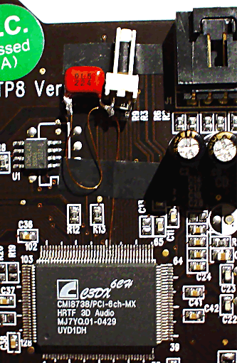
- Connect it to a capacitor (about 100 nF) which itself is attached on a PC speaker input plug as seen on the photo: One pin of the plug is directly connected to the capacitor, the other one connects to the same end of the capacitor using a resistor (about 100 Ohm). See How to built a PC speaker cable for additional information.
- Use it as a line or CD input by adding a capacitor of about 10 microfarad. The positive end of the capacitor is headed towards the sound circuits input. Depending on the type of device to be connected to the new input, the open side of the capacitor (this is, our new input) should be connected to both GND (0 Volts) as well as AVDD (5 Volts, taken from the voltage regulator, not from the slot) using a resistor of 120kOhm each.
- ... ;)
A capacitor for separating the circuit from attached devices is always required since the reference potential of the circuit is not equal to GND / 0 Volts !